
Descrizione del prodotto
Descrizione del prodotto
MAIN FEATURES:
1) Made of high quality material, non-rusting;Both flange and foot mounting available and suitable for all-round installation
2) Large output torque and high radiating efficiency
3)Precise grinding helical gear with Smooth running and low noise, no deformation,can work long time in dreadful condition
4)Nice appearance, durable service life and small volume, compact structure
5)Both 2 and 3 stage available with wide ratio range from 5 to 200
6)Different output shaft diameter available -40-50mm
7)Modular construction enlarge ratio from 5 to 1400
MAIN MATERIALS:
1)housing with aluminium alloyand cast iron material;
2)Output Shaft Material:20CrMnTi
3)Good quality no noise bearings to keep long service life
4)High performance oil seal to prevent from oil leakage
APPLICAZIONI:
G3 Series helical gear motor are wide used for all kinds of automatic equipment, such as chip removal machine, conveyor, packaging equipment, woodworking machinery, farming equipment, slurry scraper ,dryer, mixer and so on.
Foto dettagliate
Parametri del prodotto
| (n1=1400r/min 50hz) | |||||||||||||||||
| norminal ratio | 5 | 10 | 15 | 20 | 25 | 30 | 40 | 50 | 60 | 80 | 100 | 100 | 120 | 160 | 200 | ||
| 0.1kw | output shaft | Ø18 | Ø22 | ||||||||||||||
| n2* (r/min) | 282 | 138 | 92 | 70 | 56 | 46 | 35 | 28 | 23 | 18 | 14 | – | 11 | 9 | 7 | ||
| M2(Nm) | 50hz | 3.2 | 6.5 | 9.8 | 12.9 | 16.1 | 19.6 | 25.7 | 31.1 | 37.5 | 49.5 | 62.9 | – | 76.1 | 100.7 | 125.4 | |
| 60hz | 3 | 5 | 8 | 11 | 13 | 17 | 21 | 26 | 31 | 41 | 52 | – | 63 | 84 | 105 | ||
| Fr1(N) | 588 | 882 | 980 | 1180 | 1270 | 1370 | 1470 | 1570 | 2160 | 2450 | 2450 | 2450 | 2450 | 2450 | 2450 | ||
| Fr2(N) | 176 | ||||||||||||||||
| norminal ratio | 5 | 10 | 15 | 20 | 25 | 30 | 40 | 50 | 60 | 80 | 100 | 100 | 120 | 160 | 200 | ||
| 0.2kw | output shaft | Ø18 | Ø22 | Ø28 | |||||||||||||
| n2* (r/min) | 282 | 138 | 92 | 70 | 56 | 45 | 35 | 29 | 23 | 18 | 14 | 13 | 12 | 8 | 7 | ||
| M2(Nm) | 50hz | 6.5 | 12.6 | 19.1 | 26.3 | 32.6 | 38.9 | 50.4 | 63 | 75.6 | 100.8 | 103.9 | 125.4 | 150 | 200.4 | 250.7 | |
| 60hz | 5.4 | 10.5 | 16.6 | 21.9 | 27.1 | 32.4 | 42 | 52.5 | 63 | 84 | 86.6 | 104.5 | 125 | 167 | 208.9 | ||
| Fr1(N) | 588 | 882 | 980 | 1180 | 1270 | 1760 | 1860 | 1960 | 2160 | 2450 | 2450 | 2840 | 3330 | 3430 | 3430 | ||
| Fr2(N) | 196 | ||||||||||||||||
| norminal ratio | 5 | 10 | 15 | 20 | 25 | 30 | 40 | 50 | 60 | 80 | 100 | 100 | 120 | 160 | 200 | ||
| 0.4kw | output shaft | Ø22 | Ø28 | Ø32 | |||||||||||||
| n2* (r/min) | 288 | 144 | 92 | 72 | 58 | 47 | 36 | 29 | 24 | 18 | 14 | 14 | 12 | 9 | 7 | ||
| M2(Nm) | 50hz | 12.9 | 25 | 38.6 | 51.4 | 65.4 | 78.2 | 100.7 | 125.4 | 150 | 200.4 | 206.8 | 250.7 | 301.1 | 400.7 | 461.8 | |
| 60hz | 10.7 | 20.8 | 32.1 | 42.9 | 54.5 | 65.2 | 83.9 | 104.5 | 125 | 167 | 172.3 | 208.9 | 250.9 | 333.9 | 384.8 | ||
| Fr1(N) | 882 | 1180 | 1370 | 1470 | 1670 | 2550 | 2840 | 3140 | 3430 | 3430 | 3430 | 4900 | 5880 | 5880 | 5880 | ||
| Fr2(N) | 245 | ||||||||||||||||
| norminal ratio | 5 | 10 | 15 | 20 | 25 | 30 | 40 | 50 | 60 | 80 | 100 | 100 | 120 | 160 | 200 | ||
| 0.75kw | output shaft | Ø28 | Ø32 | Ø40 | |||||||||||||
| n2* (r/min) | 278 | 140 | 94 | 69 | 58 | 46 | 35 | 29 | 24 | 18 | 14 | 14 | 11 | 9 | 7 | ||
| M2(Nm) | 50hz | 24.6 | 48.2 | 72.9 | 97.5 | 122.1 | 145.7 | 187.5 | 235.7 | 282.9 | 376.1 | 387.9 | 439 | 527 | 703 | 764 | |
| 60hz | 20.5 | 40.2 | 60.7 | 81.3 | 201.8 | 121.4 | 156.3 | 196.4 | 235.7 | 313.4 | 323.2 | 366 | 439 | 585 | 732 | ||
| Fr1(N) | 1270 | 1760 | 2160 | 2350 | 2450 | 4571 | 4210 | 4610 | 5490 | 5880 | 5880 | 7060 | 7060 | 7060 | 7060 | ||
| Fr2(N) | 294 | ||||||||||||||||
| norminal ratio | 5 | 10 | 15 | 20 | 25 | 30 | 40 | 50 | 60 | 80 | 100 | 100 | 120 | 160 | 200 | ||
| 1.5kw | output shaft | Ø32 | Ø40 | Ø50 | |||||||||||||
| n2* (r/min) | 280 | 140 | 93 | 70 | 55 | 47 | 34 | 27 | 24 | 17 | 14 | 13 | 12 | 8 | 7 | ||
| M2(Nm) | 50hz | 48.2 | 97.5 | 145.7 | 193.9 | 242.1 | 272 | 351 | 439 | 527 | 703 | 724 | 878 | 1060 | 1230 | 1230 | |
| 60hz | 40.2 | 81.3 | 121.4 | 161.6 | 201.8 | 226 | 293 | 366 | 439 | 585 | 603 | 732 | 878 | 1170 | 1230 | ||
| Fr1(N) | 1760 | 2450 | 2840 | 3230 | 3820 | 5100 | 5880 | 7060 | 7060 | 7060 | 7060 | 9800 | 9800 | 9800 | 9800 | ||
| Fr2(N) | 343 | ||||||||||||||||
| norminal ratio | 5 | 10 | 15 | 20 | 25 | 30 | 40 | 50 | 60 | 80 | 100 | ||||||
| 2.2kw | output shaft | Ø40 | Ø50 | ||||||||||||||
| n2* (r/min) | 272 | 136 | 95 | 68 | 54 | 45 | 36 | 28 | 24 | 18 | 14 | ||||||
| M2(Nm) | 50hz | 67 | 133 | 200 | 266 | 332 | 399 | 515 | 644 | 773 | 1571 | 1230 | |||||
| 60hz | 56 | 111 | 167 | 221 | 277 | 332 | 429 | 537 | 644 | 858 | 1080 | ||||||
| Fr1(N) | 2160 | 3140 | 3530 | 4571 | 4700 | 6960 | 7250 | 8620 | 9800 | 9800 | 9800 | ||||||
| Fr2(N) | 392 | ||||||||||||||||
Outline and mounting dimension:
| G3FM: THREE PHASE GEAR MOTOR WITH FLANGE (n1=1400r/min) | ||||||||||||||||||||
| Power kw | output shaft | ratio | UN | F | IO | J | M | O | O1 | P | Q | R | S | T | U | W | X | Y | Y1 | |
| standard | brake | |||||||||||||||||||
| 0.1kw | Ø18 | 5–30-40-50 | 236 | 270 | 192.5 | 11 | 16.5 | 170 | 4 | 10 | 30 | 145 | 35 | 18 | 20.5 | 129 | 6 | 157 | 80 | 81 |
| Ø22 | -160-200 | 262 | 296 | 197.5 | 11 | 19 | 185 | 4 | 12 | 40 | 148 | 47 | 22 | 24.5 | 129 | 6 | 171.5 | 89.5 | 83.5 | |
| 0.2kw | Ø18 | 5- | 267 | 270 | 192.5 | 11 | 16.5 | 170 | 4 | 10 | 30 | 145 | 35 | 18 | 20.5 | 129 | 6 | 161 | 80 | 81 |
| Ø22 | -80-100 | 293 | 296 | 197.5 | 11 | 19 | 185 | 4 | 12 | 40 | 148 | 47 | 22 | 24.5 | 129 | 6 | 171.5 | 89.5 | 83.5 | |
| Ø28 | 306 | 309.5 | 208.5 | 11 | 23.5 | 215 | 4 | 15 | 45 | 170 | 50 | 28 | 31 | 129 | 8 | 198.5 | 105.5 | 88 | ||
| 0.4kw | Ø22 | 5- | 314 | 324.5 | 204 | 11 | 19 | 185 | 4 | 12 | 40 | 148 | 47 | 22 | 24.5 | 139 | 6 | 171.5 | 89.5 | 88.5 |
| Ø28 | -80-100 | 330 | 337.5 | 215 | 11 | 23.5 | 215 | 4 | 15 | 45 | 170 | 50 | 28 | 31 | 139 | 8 | 198.5 | 105.5 | 93 | |
| Ø32 | 349 | 357 | 229.5 | 13 | 28.5 | 250 | 4 | 15 | 55 | 180 | 60 | 32 | 35 | 139 | 10 | 234 | 126 | 98 | ||
| 0.75kw | Ø28 | 5- | 350.5 | 343.5 | 227.5 | 11 | 23.5 | 215 | 4 | 15 | 45 | 170 | 50 | 28 | 31 | 159 | 8 | 198.5 | 105.5 | 103 |
| Ø32 | -80-100 | 379.5 | 387 | 242 | 13 | 28.5 | 250 | 4 | 15 | 55 | 180 | 60 | 32 | 35 | 159 | 10 | 234 | 126 | 108 | |
| Ø40 | 401.5 | 408.5 | 270 | 18 | 34 | 310 | 5 | 18 | 65 | 230 | 71 | 40 | 43 | 185 | 12 | 284 | 149 | 126.5 | ||
| 1.5kw | Ø32 | 5- | 420.5 | 441 | 254 | 13 | 28.5 | 250 | 5 | 15 | 55 | 180 | 60 | 32 | 35 | 185 | 10 | 234 | 126 | 121 |
| Ø40 | -80-100 | 457.5 | 478 | 270 | 18 | 34 | 310 | 5 | 18 | 65 | 230 | 71 | 40 | 43 | 185 | 12 | 284 | 149 | 126.5 | |
| Ø50 | 485.5 | 506 | 300 | 22 | 40 | 360 | 5 | 25 | 75 | 270 | 83 | 50 | 53.5 | 185 | 14 | 325 | 173.5 | 132.5 | ||
| 2.2kw | Ø40 | 5- | 466.5 | 487 | 270 | 18 | 34 | 310 | 5 | 18 | 65 | 230 | 71 | 40 | 43 | 185 | 12 | 284 | 149 | 126.5 |
| Ø50 | -80-100 | 510.5 | 531 | 300 | 22 | 40 | 360 | 5 | 25 | 75 | 270 | 83 | 50 | 53.5 | 185 | 14 | 325 | 173.5 | 132.5 | |
| G3LM: THREE PHASE GEAR MOTOR WITH FOOT (n1=1400r/min) | ||||||||||||||||||||
| Power kw | output shaft | ratio | UN | D | E | F | J | G | H | K | P | S | T | U | V | W | X | Y | Y1 | |
| standard | brake | |||||||||||||||||||
| 0.1kw | Ø18 | 5–30-40-50 | 236 | 270 | 40 | 110 | 135 | 16.5 | 65 | 9 | 45 | 30 | 18 | 20.5 | 129 | 183 | 6 | 133 | 85 | 10 |
| Ø22 | -160-200 | 262 | 296 | 65 | 130 | 155 | 19 | 90 | 11 | 55 | 40 | 22 | 24.5 | 129 | 193 | 6 | 139.5 | 90 | 12 | |
| 0.2kw | Ø18 | 5- | 267 | 270 | 40 | 110 | 135 | 16.5 | 65 | 9 | 45 | 30 | 18 | 20.5 | 129 | 183 | 6 | 133 | 85 | 10 |
| Ø22 | -80-100 | 293 | 296 | 65 | 130 | 155 | 19 | 90 | 11 | 55 | 40 | 22 | 24.5 | 129 | 193 | 6 | 139.5 | 90 | 12 | |
| Ø28 | 306 | 309.5 | 90 | 140 | 175 | 23.5 | 125 | 11 | 65 | 45 | 28 | 31 | 129 | 203 | 8 | 170 | 110 | 15 | ||
| 0.4kw | Ø22 | 5- | 314 | 324.5 | 65 | 130 | 155 | 19 | 90 | 11 | 55 | 40 | 22 | 24.5 | 139 | 199.5 | 6 | 141.5 | 90 | 12 |
| Ø28 | -80-100 | 330 | 337.5 | 90 | 140 | 175 | 23.5 | 125 | 11 | 65 | 45 | 28 | 31 | 139 | 210 | 8 | 170 | 110 | 15 | |
| Ø32 | 349 | 357 | 130 | 170 | 208 | 28.5 | 170 | 13 | 70 | 55 | 32 | 35 | 139 | 226 | 10 | 198 | 130 | 18 | ||
| 0.75kw | Ø28 | 5- | 350.5 | 343.5 | 90 | 140 | 175 | 23.5 | 125 | 11 | 65 | 45 | 28 | 31 | 159 | 222 | 8 | 170 | 110 | 15 |
| Ø32 | -80-100 | 379.5 | 387 | 130 | 170 | 208 | 28.5 | 170 | 13 | 70 | 55 | 32 | 35 | 159 | 238.5 | 10 | 198 | 130 | 18 | |
| Ø40 | 401.5 | 408.5 | 150 | 210 | 254 | 34 | 196 | 15 | 90 | 65 | 40 | 43 | 185 | 249 | 12 | 230 | 150 | 20 | ||
| 1.5kw | Ø32 | 5- | 420.5 | 441 | 130 | 170 | 208 | 28.5 | 170 | 13 | 70 | 55 | 32 | 35 | 185 | 250.5 | 10 | 198 | 130 | 18 |
| Ø40 | -80-100 | 457.5 | 478 | 150 | 210 | 254 | 34 | 196 | 15 | 90 | 65 | 40 | 43 | 185 | 260 | 12 | 230 | 150 | 20 | |
| Ø50 | 485.5 | 506 | 160 | 230 | 290 | 40 | 210 | 18 | 100 | 75 | 50 | 53.5 | 185 | 288 | 14 | 265 | 170 | 25 | ||
| 2.2kw | Ø40 | 5- | 466.5 | 487 | 150 | 210 | 254 | 34 | 196 | 15 | 90 | 65 | 40 | 43 | 185 | 260 | 12 | 230 | 150 | 20 |
| Ø50 | -80-100 | 510.5 | 531 | 160 | 230 | 290 | 40 | 210 | 18 | 100 | 75 | 50 | 53.5 | 185 | 288 | 14 | 265 | 170 | 25 | |
| G3FS: IEC GEAR REDUCER WITH FOOT (n1=1400r/min) | |||||||||||||||||||||||||
| Power kw | output shaft | ratio | UN | B | C | F | IO | J | L | M | N | O | O1 | P | Q | R | S | S1 | T | T1 | W | W1 | X | Y | Y1 |
| 0.12kw | Ø18 | 5–30-40-50 | 147 | 95 | 115 | 154 | 11 | 16.5 | 4.5 | 170 | 140 | 4 | 10 | 30 | 145 | 35 | 18 | 11 | 20.5 | 12.8 | 6 | 4 | 163 | 80 | 86.5 |
| Ø22 | -160-200 | 173 | 95 | 115 | 164 | 11 | 19 | 4.5 | 185 | 140 | 4 | 12 | 40 | 148 | 47 | 22 | 11 | 24.5 | 12.8 | 6 | 4 | 171.5 | 89.5 | 89 | |
| 0.18kw | Ø18 | 5- | 147 | 95 | 115 | 154 | 11 | 16.5 | 4.5 | 170 | 140 | 4 | 10 | 30 | 145 | 35 | 18 | 11 | 20.5 | 12.8 | 6 | 4 | 163 | 80 | 86.5 |
| Ø22 | -80-100 | 173 | 95 | 115 | 164 | 11 | 19 | 4.5 | 185 | 140 | 4 | 12 | 40 | 148 | 47 | 22 | 11 | 24.5 | 12.8 | 6 | 4 | 171.5 | 89.5 | 89 | |
| Ø28 | 186.5 | 95 | 115 | 186 | 11 | 23.5 | 4.5 | 215 | 140 | 4 | 15 | 45 | 170 | 50 | 28 | 11 | 31 | 12.8 | 8 | 4 | 198.5 | 105.5 | 93.5 | ||
| 0.37kw | Ø22 | 5- | 181.5 | 110 | 130 | 164 | 11 | 19 | 4.5 | 185 | 160 | 4 | 12 | 40 | 148 | 47 | 22 | 14 | 24.5 | 16.3 | 6 | 5 | 201 | 89.5 | 99 |
| Ø28 | -80-100 | 198 | 110 | 130 | 186 | 11 | 23.5 | 4.5 | 215 | 160 | 4 | 15 | 45 | 170 | 50 | 28 | 14 | 31 | 16.3 | 8 | 5 | 198.5 | 105.5 | 103.5 | |
| Ø32 | 216.5 | 110 | 130 | 215 | 13 | 28.5 | 4.5 | 250 | 160 | 4 | 15 | 55 | 180 | 60 | 32 | 14 | 35 | 16.3 | 10 | 5 | 234 | 126 | 108.5 | ||
| 0.75kw | Ø28 | 5- | 206.5 | 130 | 165 | 185 | 11 | 23.5 | 4.5 | 215 | 200 | 4 | 15 | 45 | 170 | 50 | 28 | 19 | 31 | 21.8 | 8 | 6 | 216.5 | 105.5 | 123.5 |
| Ø32 | -80-100 | 235 | 130 | 165 | 215 | 13 | 28.5 | 4.5 | 250 | 200 | 4 | 15 | 55 | 180 | 60 | 32 | 19 | 35 | 21.8 | 10 | 6 | 236.5 | 126 | 128.5 | |
| Ø40 | 260.5 | 130 | 165 | 270 | 18 | 34 | 4.5 | 310 | 200 | 5 | 18 | 65 | 230 | 71 | 40 | 19 | 43 | 21.8 | 12 | 8 | 284 | 149 | 134 | ||
| 1.5kw | Ø32 | 5- | 252 | 130 | 165 | 215 | 13 | 28.5 | 4.5 | 250 | 200 | 5 | 15 | 55 | 180 | 60 | 32 | 24 | 35 | 27.3 | 10 | 8 | 236.5 | 126 | 128.5 |
| Ø40 | -80-100 | 293.5 | 130 | 165 | 270 | 18 | 34 | 4.5 | 310 | 200 | 5 | 18 | 65 | 230 | 71 | 40 | 24 | 43 | 27.3 | 12 | 8 | 284 | 149 | 134 | |
| Ø50 | 321.5 | 130 | 165 | 300 | 22 | 40 | 4.5 | 360 | 200 | 5 | 25 | 75 | 270 | 83 | 50 | 24 | 53.5 | 27.3 | 14 | 8 | 323.5 | 173.5 | 140 | ||
| 2.2kw | Ø40 | 5- | 290 | 180 | 215 | 270 | 18 | 34 | 5.5 | 310 | 250 | 5 | 18 | 65 | 230 | 71 | 40 | 28 | 43 | 31.3 | 12 | 8 | 284 | 149 | 134 |
| Ø50 | -80-100 | 334 | 180 | 215 | 300 | 22 | 40 | 5.5 | 360 | 250 | 5 | 25 | 75 | 270 | 83 | 50 | 28 | 53.5 | 31.3 | 14 | 8 | 323.5 | 173.5 | 140 | |
| G3LS: IEC GEAR REDUCER WITH FOOT (n1=1400r/min) | |||||||||||||||||||||||||
| Power kw | output shaft | ratio | UN | B | C | D | E | F | G | H | J | K | L | N | P | S | S1 | T | T1 | W | W1 | X | Y | Y1 | Z |
| 0.12kw | Ø18 | 5–30-40-50 | 147 | 95 | 115 | 40 | 110 | 135 | 65 | 9 | 16.5 | 45 | 4.5 | 140 | 30 | 18 | 11 | 20.5 | 12.8 | 6 | 4 | 138.5 | 85 | 10 | M8 |
| Ø22 | -160-200 | 173 | 95 | 115 | 65 | 130 | 154 | 90 | 11 | 19 | 55 | 4.5 | 140 | 40 | 22 | 11 | 24.5 | 12.8 | 6 | 4 | 141 | 90 | 12 | M8 | |
| 0.18kw | Ø18 | 5- | 147 | 95 | 115 | 40 | 110 | 135 | 65 | 9 | 16.5 | 45 | 4.5 | 140 | 30 | 18 | 11 | 20.5 | 12.8 | 6 | 4 | 138.5 | 85 | 10 | M8 |
| Ø22 | -80-100 | 173 | 95 | 115 | 65 | 130 | 154 | 90 | 11 | 19 | 55 | 4.5 | 140 | 40 | 22 | 11 | 24.5 | 12.8 | 6 | 4 | 141 | 90 | 12 | M8 | |
| Ø28 | 186.5 | 95 | 115 | 90 | 140 | 175 | 125 | 11 | 23.5 | 65 | 4.5 | 140 | 45 | 28 | 11 | 31 | 12.8 | 8 | 4 | 170 | 110 | 15 | M8 | ||
| 0.37kw | Ø22 | 5- | 181.5 | 110 | 130 | 65 | 130 | 154 | 90 | 11 | 19 | 55 | 4.5 | 160 | 40 | 22 | 14 | 24.5 | 16.3 | 6 | 5 | 151 | 90 | 12 | M8 |
| Ø28 | -80-100 | 198 | 110 | 130 | 90 | 140 | 175 | 125 | 11 | 23.5 | 65 | 4.5 | 160 | 45 | 28 | 14 | 31 | 16.3 | 8 | 5 | 170 | 110 | 15 | M8 | |
| Ø32 | 216.5 | 110 | 130 | 130 | 170 | 208 | 170 | 13 | 28.5 | 70 | 4.5 | 160 | 55 | 32 | 14 | 35 | 16.3 | 10 | 5 | 198 | 130 | 18 | M8 | ||
| 0.75kw | Ø28 | 5- | 206.5 | 130 | 165 | 90 | 140 | 175 | 125 | 11 | 23.5 | 65 | 4.5 | 200 | 45 | 28 | 19 | 31 | 21.8 | 8 | 6 | 186.5 | 110 | 15 | M10 |
| Ø32 | -80-100 | 235 | 130 | 165 | 130 | 170 | 208 | 170 | 13 | 28.5 | 70 | 4.5 | 200 | 55 | 32 | 19 | 35 | 21.8 | 10 | 6 | 201.5 | 130 | 18 | M10 | |
| Ø40 | 260.5 | 130 | 165 | 150 | 210 | 254 | 196 | 15 | 34 | 90 | 4.5 | 200 | 65 | 40 | 19 | 43 | 21.8 | 12 | 8 | 230 | 150 | 20 | M10 | ||
| 1.5kw | Ø32 | 5- | 252 | 130 | 165 | 130 | 170 | 208 | 170 | 13 | 28.5 | 70 | 4.5 | 200 | 55 | 32 | 24 | 35 | 27.3 | 10 | 8 | 201.5 | 130 | 18 | M10 |
| Ø40 | -80-100 | 293.5 | 130 | 165 | 150 | 210 | 254 | 196 | 15 | 34 | 90 | 4.5 | 200 | 65 | 40 | 24 | 43 | 27.3 | 12 | 8 | 230 | 150 | 20 | M10 | |
| Ø50 | 321.5 | 130 | 165 | 160 | 230 | 290 | 210 | 18 | 40 | 100 | 4.5 | 200 | 75 | 50 | 24 | 53.5 | 27.3 | 14 | 8 | 265 | 170 | 25 | M10 | ||
| 2.2kw | Ø40 | 5- | 290 | 180 | 215 | 150 | 210 | 254 | 196 | 15 | 34 | 90 | 5.5 | 250 | 65 | 40 | 28 | 43 | 31.3 | 12 | 8 | 230 | 150 | 20 | M12 |
| Ø50 | -80-100 | 334 | 180 | 215 | 160 | 230 | 290 | 210 | 18 | 40 | 100 | 5.5 | 250 | 75 | 50 | 28 | 53.5 | 31.3 | 14 | 8 | 265 | 170 | 25 | M12 | |
Profilo Aziendale
We are a professional reducer manufacturer located in HangZhou, ZHangZhoug province.Our leading products is full range of RV571-150 worm reducers , also supplied GKM hypoid helical gearbox, GRC inline helical gearbox, PC units, UDL Variators and AC Motors, G3 helical gear motor.Products are widely used for applications such as: foodstuffs, ceramics, packing, chemicals, pharmacy, plastics, paper-making, construction machinery, metallurgic mine, environmental protection engineering, and all kinds of automatic lines, and assembly lines.With fast delivery, superior after-sales service, advanced producing facility, our products sell well both at home and abroad. We have exported our reducers to Southeast Asia, Eastern Europe and the Middle East and so on.Our aim is to develop and innovate on the basis of high quality, and create a good reputation for reducers.
Workshop:
Exhibition
ZheJiang PTC Fair:
Imballaggio e spedizione
Servizio post-vendita
1. Tempi di manutenzione e garanzia:Entro 1 anno dal ricevimento della merce.
2. Altri servizi: Including modeling selection guide, installation guide, and problem resolution guide, etc
FAQ
1. D: Potete realizzare il prodotto in base al disegno del cliente?
A: Sì, offriamo un servizio personalizzato per i clienti. Possiamo utilizzare la targhetta del cliente per i riduttori.
2. D: Quali sono le vostre condizioni di pagamento?
A: 30% acconto prima della produzione, saldo T/T prima della consegna.
3. D: Siete una società commerciale o un produttore?
A: Siamo un'azienda produttrice dotata di attrezzature all'avanguardia e di personale esperto.
4. D: Qual è la vostra capacità produttiva?
A:4000-5000 PCS/MONTH
5. D: È disponibile un campione gratuito?
A: Sì, possiamo fornire un campione gratuito se il cliente accetta di pagare le spese di spedizione.
6. D: Possiede qualche certificato?
A: Sì, disponiamo del certificato CE e del rapporto di certificazione SGS.
Informazioni sui contatti:
La signora Lingel Pan
Per qualsiasi domanda, non esitate a contattarmi. Grazie mille per la gentile attenzione che avete dedicato alla nostra azienda!
| Applicazione: | Motor, Machinery, Marine, Agricultural Machinery, Power Transmission Applications |
|---|---|
| Durezza: | Superficie del dente indurita |
| Installazione: | Vertical or Horizontal Type |
| Disposizione: | Coassiale |
| Forma dell'ingranaggio: | Ingranaggio elicoidale |
| Fare un passo: | Two Stage- Three Stage |
| Esempi: |
US$ 35/Piece
1 pezzo (ordine minimo) | |
|---|
| Personalizzazione: |
Disponibile
| Richiesta personalizzata |
|---|
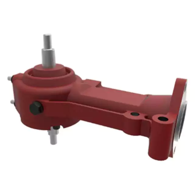
Considerazioni sui cambi per macchine agricole per impieghi gravosi
Le applicazioni agricole gravose richiedono riduttori robusti e affidabili, in grado di resistere a carichi elevati, condizioni difficili e un utilizzo frequente. Ecco i principali aspetti da considerare nella scelta dei riduttori per l'agricoltura gravosa:
- Capacità di carico: I riduttori per impieghi gravosi devono avere un'elevata capacità di carico per far fronte alle esigenze delle macchine agricole, come fresatrici, aratri e mietitrebbie.
- Durata del materiale: I cambi devono essere costruiti con materiali resistenti, come acciaio temprato o ghisa, in grado di sopportare le sollecitazioni e gli urti associati a lavori gravosi.
- Sigillatura e protezione: Meccanismi di tenuta e protezione efficaci, come guarnizioni e sigilli robusti, impediscono l'ingresso di sporco, acqua e contaminanti che possono causare usura e danni prematuri.
- Sistema di lubrificazione: Un sistema di lubrificazione affidabile ed efficiente è fondamentale per i riduttori per impieghi gravosi, al fine di garantire una lubrificazione adeguata dei componenti sottoposti a carichi e temperature elevati.
- Dissipazione del calore: Le applicazioni gravose generano una notevole quantità di calore. I riduttori devono essere dotati di efficienti meccanismi di dissipazione del calore, come alette di raffreddamento o radiatori dell'olio, per prevenire il surriscaldamento e mantenere le prestazioni.
- Progettazione e costruzione: La progettazione del riduttore dovrebbe prevedere un alloggiamento rinforzato, cuscinetti di dimensioni maggiori e ingranaggi robusti per gestire carichi pesanti senza compromettere l'integrità strutturale.
- Allineamento e montaggio: Un corretto allineamento e montaggio sono essenziali per garantire una trasmissione di potenza fluida ed efficiente. Un disallineamento può causare un'usura maggiore e una riduzione della durata del riduttore.
- Accessibilità per la manutenzione: I riduttori per impieghi gravosi devono essere progettati per consentire un facile accesso per la manutenzione. Caratteristiche come coperchi rimovibili e punti di ispezione semplificano la manutenzione e le riparazioni.
- Compatibilità: I riduttori devono essere compatibili con i macchinari e le applicazioni specifiche per cui verranno utilizzati. Rapporti di trasmissione e configurazioni dell'albero di uscita personalizzabili ne aumentano la versatilità.
- Affidabilità e longevità: I riduttori per impieghi gravosi devono essere costruiti per durare, con una lavorazione di qualità e componenti in grado di resistere alle condizioni impegnative delle operazioni agricole.
- Sicurezza: Le caratteristiche di sicurezza, come le protezioni e i meccanismi di arresto di emergenza, sono essenziali per proteggere gli operatori e il personale nelle vicinanze da potenziali pericoli.
- Considerazioni ambientali: Nella progettazione dei cambi è necessario tenere conto delle normative ambientali e degli standard sulle emissioni, al fine di minimizzare l'impatto sull'ambiente.
- Rapporto costi-efficacia: Sebbene i riduttori per impieghi gravosi richiedano un investimento iniziale maggiore, la loro durata e le loro prestazioni contribuiscono alla redditività a lungo termine, riducendo i tempi di inattività e la necessità di sostituzioni frequenti.
Valutando attentamente questi fattori, gli agricoltori possono selezionare i riduttori per impieghi gravosi più adatti, che migliorano la produttività e l'affidabilità delle loro attività agricole.
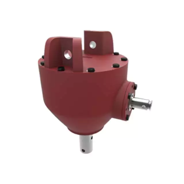
Potential Challenges in Maintenance and Repairs of Agricultural Gearboxes
Maintenance and repairs of gearboxes in agriculture can pose several challenges:
- Harsh Environments: Agricultural machinery operates in challenging environments with exposure to dirt, debris, moisture, and varying temperatures. These conditions can accelerate wear and corrosion, necessitating frequent maintenance.
- Heavy Workloads: Gearboxes in farming equipment often handle heavy workloads, leading to increased stress on components. This can result in faster wear and tear, requiring more frequent inspections and part replacements.
- Accessibility: Some gearboxes are located in hard-to-reach areas of machinery. This makes regular maintenance and repairs more challenging, as technicians may need specialized tools and equipment to access and service the gearboxes.
- Specialized Knowledge: Proper maintenance of agricultural gearboxes requires specialized knowledge and skills. Inadequate understanding of gearbox mechanics and maintenance practices can lead to improper repairs, reducing the gearbox’s lifespan and efficiency.
- Costs: Repairing or replacing gearbox components can be costly, especially for heavy-duty agricultural machinery. Farmers need to consider both the direct costs of parts and labor, as well as potential downtime during repair processes.
- Downtime: The downtime required for gearbox maintenance or repairs can impact farming operations, especially during critical planting or harvesting seasons. Efficient scheduling and backup equipment can help mitigate this challenge.
- Availability of Parts: Obtaining replacement parts for older or less common gearbox models can be challenging. Farmers may need to source parts from specialized suppliers, leading to potential delays in repairs.
Addressing these challenges requires proactive maintenance planning, regular inspections, proper training of maintenance personnel, and sourcing spare parts in advance.
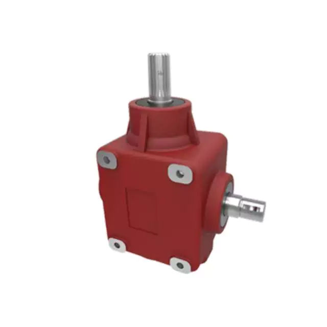
Key Features of a Durable and Reliable Agricultural Gearbox
A durable and reliable agricultural gearbox is crucial for the efficient operation of farming equipment and machinery. The following key features contribute to the durability and reliability of agricultural gearboxes:
- High-Quality Materials: Agricultural gearboxes are often exposed to harsh conditions, including dust, debris, and varying weather. Using high-quality materials, such as strong alloy steels, can enhance the gearbox’s resistance to wear, corrosion, and other forms of deterioration.
- Rugged Construction: The gearbox should have a robust and rugged construction to withstand the stresses and strains associated with agricultural tasks. Reinforced housings, precision machining, and robust seals can help prevent damage and ensure longevity.
- Effective Lubrication System: Proper lubrication is vital to reduce friction, dissipate heat, and prevent premature wear. Agricultural gearboxes should be equipped with efficient lubrication systems that ensure all components are adequately lubricated, even during extended operation.
- Sigillatura e protezione: Dust, dirt, and moisture are common challenges in agricultural environments. Effective sealing mechanisms, such as gaskets and seals, prevent contaminants from entering the gearbox and protect internal components from damage.
- Dissipazione del calore: The gearbox should be designed to dissipate heat effectively, especially during prolonged operation. Overheating can lead to lubrication breakdown and premature wear. Cooling fins and adequate ventilation can help maintain optimal operating temperatures.
- Gear Quality and Precision: High-quality gears with accurate tooth profiles and precision manufacturing ensure smooth and efficient power transmission. Properly machined gears reduce noise, vibration, and the risk of gear failures.
- Advanced Gear Design: Some agricultural gearboxes may feature advanced gear designs, such as helical or planetary gears. These designs offer improved efficiency, reduced noise, and increased load-bearing capacity compared to traditional spur gears.
- Protezione da sovraccarico: Incorporating overload protection mechanisms, such as shear pins or clutch systems, can prevent damage to the gearbox and other connected components in case of sudden high loads or jams.
- Easy Maintenance Access: The gearbox should be designed with maintenance in mind. Accessible inspection points, drain plugs, and fill ports make it easier for operators to perform routine maintenance tasks.
Manufacturers often engineer agricultural gearboxes to meet these requirements, ensuring that they can withstand the demanding conditions of farming operations and contribute to the reliable performance of agricultural machinery.


editor by CX 2023-11-02